

 Français
 Español
 Deutsch


Content
- 1 The Short Answer: Four Steps, Three Numbers, One Order
- 2 What Is Actually Inside a Thread Repair Kit
- 3 Read the Damage Before You Cut Metal
- 4 How to Use a Thread Repair Kit, Step by Step
- 4.1 Step 1: Confirm the kit against the insert
- 4.2 Step 2: Mark the drill depth
- 4.3 Step 3: Drill out the damaged thread
- 4.4 Step 4: Chamfer the mouth
- 4.5 Step 5: Tap the new thread
- 4.6 Step 6: Clean the hole until a cloth comes out clean
- 4.7 Step 7: Install the insert
- 4.8 Step 8: Remove the tang and verify
- 5 How Deep Should the Insert Sit? Engagement Depth in Practice
- 6 Matching the Insert to the Base Material
- 7 The Tools That Decide the Outcome
- 8 Seven Mistakes That Turn a Repair Into a Rebuild
- 9 Inspection, Torque and Handover
- 10 Buying Thread Repair Kits in Volume: What Maintenance and Purchasing Teams Should Ask
- 11 Frequently Asked Questions About Thread Repair Kits
- 11.1 How long does it take to use a thread repair kit?
- 11.2 Can I repair a hole that has already been repaired once?
- 11.3 Do I need a special drill bit?
- 11.4 Is a thread repair kit suitable for aluminium?
- 11.5 Why does my insert sit above the surface?
- 11.6 Can I use a thread repair kit on a through hole in a fluid passage?
- 12 Further Reading and Workshop Resources
A stripped M8 hole in an aluminium housing rarely announces itself politely. The bolt spins free on the final torque turn, the internal thread looks smeared rather than cut, and someone in the workshop asks whether the part has to be scrapped. Most of the time it does not. Knowing how to use a thread repair kit properly turns a twenty-minute bench job into a permanent repair, while rushing the same job turns a recoverable hole into an oversized one that no insert will hold.
The short version: you drill out the damaged thread with the bit sized for the insert, cut a larger thread with the matching repair tap, remove every chip from the hole, and install an insert that restores the original bolt size. The fastener, the thread class and the torque figure stay the same. Only the material that grips the bolt changes.
The rest of this guide is about the details that decide whether the insert stays put for the life of the assembly: matching the kit to the insert family, marking drill depth instead of guessing it, and treating hole cleaning as a real step rather than an afterthought. In our experience at the manufacturing bench, those three details explain most of the failed repairs that come back for inspection.
A thread repair succeeds or fails in the hole preparation, not in the insert itself.
The Short Answer: Four Steps, Three Numbers, One Order
A thread repair kit is a small, self-contained system built around one insert size. Whichever family the kit belongs to, the sequence is the same four operations, and they only work in this order.
- Drill out the damaged thread to the diameter printed on the kit chart for that insert size.
- Chamfer the hole mouth so the tap starts square and the insert can enter without cross-threading.
- Tap the new, larger internal thread with the special repair tap that comes with the kit.
- Install the insert with its dedicated driver, then verify with the original bolt or a thread gauge.
Three numbers control the whole job, and all three must be confirmed before the drill touches metal: nominal diameter, thread pitch, and insert length. Diameter decides the bolt that will fit afterwards. Pitch decides whether you have a metric fine thread or a metric coarse thread of the same size, which is where many M10 repairs go wrong, because M10 x 1.0, M10 x 1.25 and M10 x 1.5 are three different kits. Insert length decides how much thread engagement the repair will carry.
The order is not negotiable
Drilling after tapping is impossible, and tapping after inserting is worse. There is also a hidden order requirement that kit instructions often bury in a footnote: cleaning sits between tapping and installing, and skipping it is the single most common reason a coil binds halfway in. Chips left in the hole act like a locking compound applied in the wrong place.
| Stage | Tool used | What it guarantees |
|---|---|---|
| Drill | Kit drill bit, depth taped | Correct minor diameter for the repair tap |
| Chamfer | Countersink or kit chamfer tool | Square tap entry and a flush insert seat |
| Tap | Repair tap from the kit | Thread form that matches the insert outside diameter |
| Clean | Air, brush, solvent | No chips under the insert or in the bolt path |
| Install | Driver, mandrel or setting tool | Insert seated at the correct depth without preload |
Confirm diameter, pitch and length before drilling; after the drill moves, those three numbers are fixed.
What Is Actually Inside a Thread Repair Kit
A kit is more than a box of parts. Each item exists to serve one specific insert family, and mixing components between families is how holes get ruined. Four items appear in almost every kit: a drill bit sized to the insert, a specially ground tap with an oversize outside diameter, a set of inserts, and an installation tool.
The four core components
- Drill bit – not a standard tapping drill. Its diameter equals the minor diameter of the repair tap, not the minor diameter of the original thread.
- Repair tap – cuts the holding thread that the insert screws into. Its size is unique to the insert, which is why ordinary taps cannot substitute.
- Inserts – the replaceable thread surface. Sold in packs, and worth buying in the length that matches your wall thickness rather than trimming longer ones.
- Installation tool – a mandrel for coiled inserts, a driver or setting tool for solid inserts. The tool controls depth and, on keyed designs, locks the insert in place.
Three insert families, three different repair logics
A helical wire insert replaces the thread surface with a diamond-shaped stainless coil that shares load across many turns. A self-tapping solid insert cuts its own holding thread into the prepared hole, which suits softer base materials and repairs where the surrounding wall is thin. A key-locking insert uses small keys driven down through the insert body to mechanically lock it against rotation, which is the usual answer for high-vibration or safety-relevant joints.
| Family | How it holds | Suits | Watch out for |
|---|---|---|---|
| Wire (helical coil) insert | Coil expands against the tapped thread | Steel, cast iron, aluminium with enough wall | Tang left in blind holes; coil driven too deep |
| Self-tapping solid insert | Cuts its own thread in the prepared hole | Aluminium, magnesium, soft castings | Needs a precise hole; hard materials resist it |
| Key-locking insert | Keys driven through the body lock rotation | Vibration, aerospace, high-load joints | Key slots must be aligned with the driver |
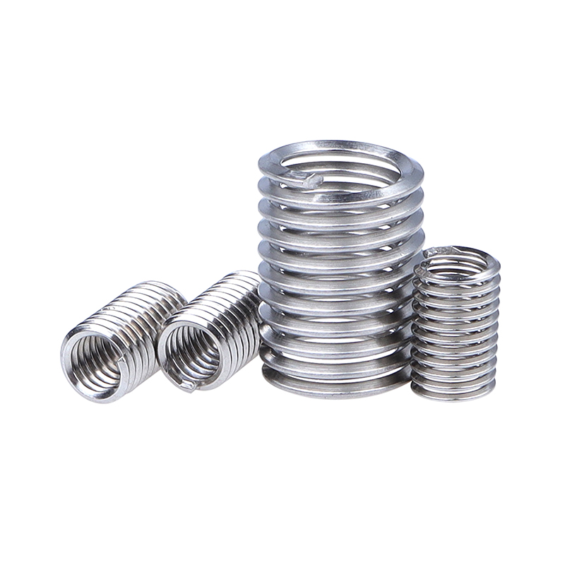 Tangless Wire Thread Insert for Blind-Hole Thread RepairNo installation tang to break off or retrieve from blind holes; installs from either end with specialized tools and avoids tang-removal steps.View Product →
A tangless wire insert is worth mentioning here because it removes one whole failure mode from the process. With no installation tang, there is nothing to break off and nothing to retrieve from a blind hole, which matters when the hole ends inside a housing you cannot open.
Buy the kit for the insert family you will standardise on, not the other way round.
Read the Damage Before You Cut Metal
Ten minutes of assessment saves a scrapped component. Three questions decide whether a repair kit is the right answer: what thread was originally there, how much sound material surrounds the hole, and whether the part is safety-critical.
Measure diameter and pitch separately
A caliper gives you the outside diameter of the bolt or the inside diameter of the hole. It does not give you pitch. Use a pitch gauge, or place the bolt against a steel rule and count the crests across 10 mm or one inch. Metric coarse M8 is 1.25 mm pitch; metric fine M8 is 1.0 mm. They look identical at arm's length and require different kits. On imperial fasteners, confirm UNC against UNF the same way before ordering.
Judge the wall thickness honestly
Every repair enlarges the hole. A wire insert for M8 typically needs a drilled hole around 8.3 to 8.4 mm and a tapped hole just over 9.5 mm, so the boss must comfortably contain that diameter. If the hole sits close to an edge, or the wall is thinner than roughly one and a half times the final tapped diameter, a solid self-tapping insert or a redesign is usually the safer route than a coil.
Know when to stop
- Cracks radiating from the hole – a repair insert does not restore a cracked boss.
- Heat-treated or high-strength parts where drilling may alter the heat treatment locally.
- A hole already repaired once with a larger insert – there is a practical limit of one step up.
- Safety-critical joints with no engineering approval for a repair, particularly in aerospace and brake systems.
If the boss cannot contain the tapped hole with margin to spare, change the method rather than the drill.
How to Use a Thread Repair Kit, Step by Step
The procedure below applies to the common wire insert kit and adapts easily to solid inserts, where the tap is often replaced by the insert's own cutting action. Work on a clean bench, with the component supported so it cannot rock.
Step 1: Confirm the kit against the insert
Check that the drill, tap and inserts in the box belong together. Insert lengths are not interchangeable: a 1.5D insert in a 2D-deep hole leaves the bolt short of full engagement, and a long insert in a blind hole bottoms out before it seats. Compare the insert outside diameter to the tap with a caliper if the packaging is worn.
Step 2: Mark the drill depth
Wrap tape around the drill bit at the required depth, measured from the tip. Add roughly 2 to 3 mm of allowance beyond the insert length so the thread has somewhere to go but the drill does not break through a blind wall. On a through hole, mark anyway; the tape tells you when to stop pushing.
Step 3: Drill out the damaged thread
Clamp the part, align the drill with the original axis, and keep it square in both planes. A drill that wanders leaves an oval hole and a tap that cuts unevenly. Use a slow, steady speed with a drop of cutting fluid; continuous swarf tells you the cut is healthy. Clear the flutes often, especially in aluminium, where chips weld to the drill.
Step 4: Chamfer the mouth
A shallow countersink, roughly 0.5 mm deep and slightly wider than the thread, does two things: it gives the tap a square start and it stops the top coil from sitting proud of the surface. On solid inserts, the chamfer also receives the insert flange.
Step 5: Tap the new thread
Apply cutting oil generously, start the tap by hand, and check squareness from two directions before applying real force. Turn forward half a turn, back a quarter turn, and repeat. The reverse motion breaks the chip instead of packing it into the flutes. Continue until the tap reaches the marked depth, then withdraw it slowly and clean the flutes before the next hole.
Step 6: Clean the hole until a cloth comes out clean
Blow out the hole from the bottom with compressed air, brush the thread with a nylon or brass brush, and wipe with a lint-free cloth dampened with solvent. Repeat until the cloth stays clean. In blind holes, finish with a small magnet or a dab of grease on a probe to lift the last chips.
Step 7: Install the insert
For a coiled insert, wind it onto the mandrel until the driving tang engages, then thread it in until the top turn sits half a turn to one full turn below the surface. Never drive it in by force; if resistance rises sharply, back out, clean and start again. For a solid self-tapping insert, thread it onto the driver, align it square, and turn steadily until the top is flush with the chamfer. For a key-locking insert, drive the keys down after the body is seated.
Step 8: Remove the tang and verify
Break the driving tang with the punch supplied and retrieve it with the hooked tool or a magnet. Then run the original bolt in by hand; it should turn smoothly with light drag and no catching. Finish with a thread gauge if the joint is inspected, and record the insert size and depth for the maintenance file.
If the insert fights you at any point, stop and clean the hole; forcing it only enlarges the damage.
How Deep Should the Insert Sit? Engagement Depth in Practice
Engagement depth is the quiet variable in every thread repair. A correctly installed insert that only engages four or five threads will pull out long before its rated load, while the same insert seated through ten or twelve threads behaves like a new boss. The relationship is not linear either: the first few threads carry a disproportionate share of the load, so losing them hurts far more than the arithmetic suggests. Base material matters just as much, because aluminium distributes load over fewer sound threads than steel does. The figures in the chart below are the working minimums many shops use when choosing insert length; always confirm them against your insert supplier's data and your own torque requirements.
| Base material | Relative engagement depth | Minimum | Practical note |
|---|---|---|---|
| Low-strength aluminium alloy | 2.0D | Use longer inserts; consider solid self-tapping type | |
| High-strength aluminium, cast iron | 1.5D | Standard kit length usually sufficient | |
| Mild and low-alloy steel | 1.25D | Watch for thread run-out in blind holes | |
| Stainless and high-strength alloy | 1.0D | Full thread engagement, no shortcuts on tapping |
Read the chart as a minimum, not a target. The aluminium row is the one that changes buying decisions most often, because a 1.5D insert that works perfectly in a steel bracket is genuinely marginal in a soft casting. Where the design allows, moving one length up in aluminium costs very little and buys a large margin in pull-out strength. Where the wall will not allow it, the better answer is usually a solid self-tapping insert, which cuts a full thread through the available depth instead of relying on a coil.
The second pattern in the chart is about load distribution rather than raw strength. In steel, the parent material is stiff enough that the load spreads over the engaged turns quickly, so 1.0D is defensible when the thread is fully formed and the bolt is torqued correctly. In aluminium, the material yields slightly under the first turns, which shifts load to the remaining threads; that is why the recommendation stretches to 2.0D rather than 1.5D.
Depth also interacts with hole type. In a blind hole, the usable depth is always less than the drilled depth, because the tap cannot cut right to the bottom without a chip trap forming. As a practical rule, plan for the tap to reach two or three threads beyond the insert top, and never let the insert bottom out, since a coil that touches the floor of the hole will buckle slightly and grip unevenly. In a through hole, the constraint reverses: the insert must not protrude into a cavity where it could be hit by a mating part or block a passage.
Finally, engagement is only half of the strength story; the other half is what the insert sits in. A 2.0D insert in a boss with a visible casting defect will still fail, and an insert installed with a partially formed thread will pull out at a fraction of its rating regardless of depth. That is why the chart is best used together with a visual check of the tapped thread: sharp, complete crests, no torn material, and no chatter marks.
In aluminium, one extra insert length buys more pull-out strength than any change to installation technique.
Matching the Insert to the Base Material
The same kit procedure produces very different results depending on what the hole is cut into. Soft materials reward longer engagement and gentler tapping; hard materials punish an undersized drill with broken taps.
Case A: aluminium casting, blind hole
|
Case B: steel bracket, through hole
|
Material notes worth keeping on the bench
- Cast iron – graphite dust contaminates cutting oil; clean and re-oil between holes.
- Stainless steel – work-harden quickly; keep the tap moving and never let it rub.
- Magnesium – chips are a fire risk; use dedicated extraction and never dry-blow near ignition sources.
- Plated or coated parts – the drill removes the coating locally, so plan a touch-up to protect against corrosion.
Match insert length and type to the base material first, then to the bolt size.
The Tools That Decide the Outcome
Kits are sold with basic tooling, but production workshops quickly learn that the driver and the tap do most of the work. A worn mandrel that slips on the coil leaves burrs and destroys the insert's internal thread before it is even seated.
Installation tools
A wire insert mandrel consists of a threaded nose that engages the driving tang and a shoulder that stops the insert at the correct depth. Check the nose thread for wear every few hundred inserts; a rounded nose is the usual cause of a coil that starts crooked. Solid self-tapping inserts use a driver that engages the internal thread and a setting tool that seats the insert flush without over-driving it into the chamfer.
Extraction and replacement
Sooner or later an insert goes in badly and has to come out. Extraction tools cut into the insert bore and grip it so it can be unscrewed without enlarging the hole. Done carefully, a replacement insert of the same size can go straight back into the existing tapped thread, which makes extraction the cheapest possible recovery.
Taps and drills deserve the same attention
Repair taps are ground with a lead chamfer matched to the insert. A tap that has been used on hundreds of holes, or dropped on the floor, will cut undersize and the insert will feel tight for its whole length. Keep two taps per commonly used size in rotation and retire them when a new insert no longer threads in by hand.
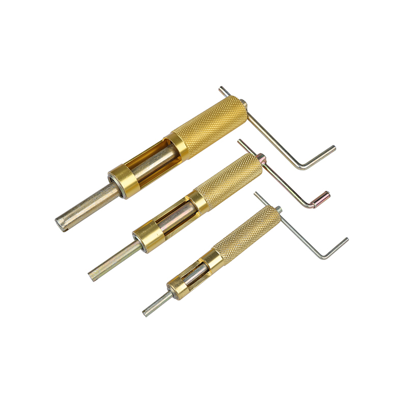 Wire Thread Insert Installation Tool for Accurate AssemblyPrecision-guided tool that screws wire inserts into pre-tapped holes, supports M3–M24 inserts and helps standardise installation across workshop repairs and assembly.View Product →
The same logic applies across the whole tool set. A workshop that standardises on one insert family, one driver design and one tap type per size will produce consistent repairs across shifts, which matters far more than the brand printed on the box.
Replace worn drivers and taps on a schedule; the insert is rarely the part that fails first.
Seven Mistakes That Turn a Repair Into a Rebuild
Most of these appear in the same order on a bench where someone is learning the process. Each one has a specific, cheap fix.
- Using the wrong drill. A standard tapping drill removes too little or too much material and the repair tap cuts an incomplete thread. Always use the drill supplied or specified for that insert.
- Tapping at an angle. A tap that starts a few degrees off produces a hole whose thread is deeper on one side, and the insert will follow that error.
- Leaving chips in the hole. The insert compresses them, loses contact area and sits proud. Clean until the cloth stays clean.
- Driving the insert too deep. The top coil should sit just below the surface. Deeper means fewer usable threads and, in blind holes, a bottomed-out insert.
- Skipping the chamfer. Without it the first thread of the insert is often damaged during entry.
- Forgetting the tang. A tang left in a blind hole blocks the bolt. Retrieve it before the part leaves the bench.
- Torquing to the original figure blindly. If the surrounding material is thin or soft, confirm the applied torque with engineering instead of assuming.
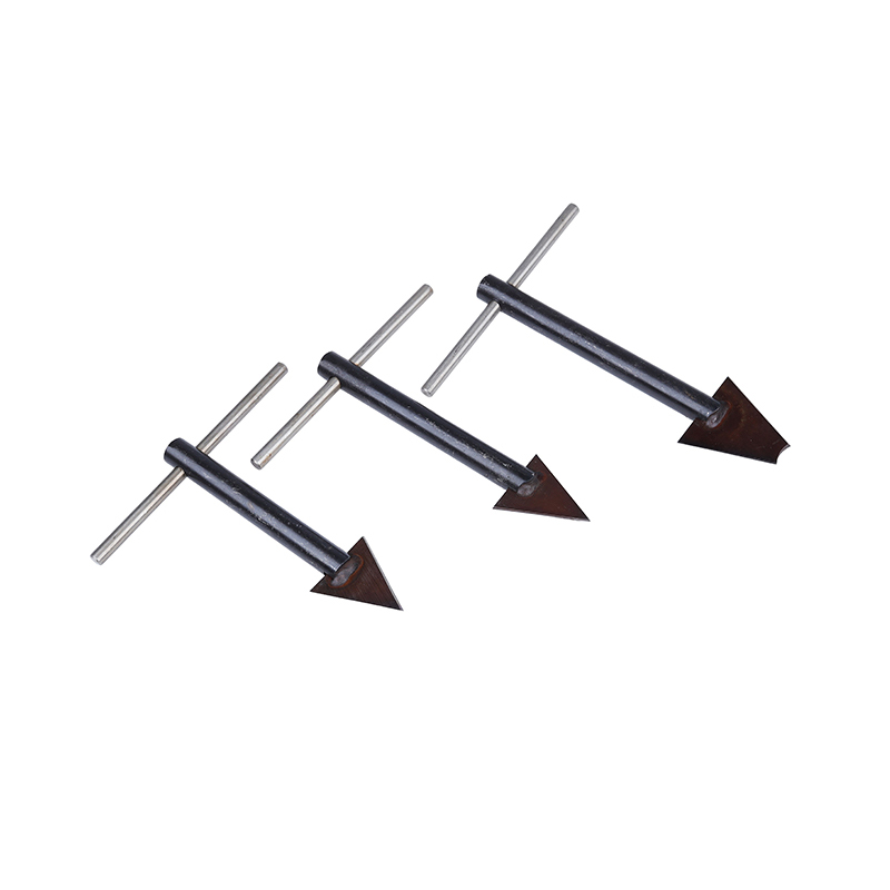 Thread Insert Removal Tool for Damaged or Stuck InsertsPrecision-gripping extraction tool for incorrectly installed, damaged or stuck M3–M16 inserts, designed to protect base threads during thread repair and replacement.View Product →
Extraction is the safety net for items three and four on that list, and it is worth keeping one extraction tool per common insert size on the shelf rather than ordering it after the mistake happens. A recovered hole costs minutes; a re-drilled oversize hole often costs the part.
Six of the seven mistakes happen before the insert enters the hole, which is where to spend your attention.
Inspection, Torque and Handover
A repair is not finished when the insert is seated; it is finished when the joint has been verified and the record exists. Three checks take under a minute each.
Thread check
Run the original bolt in by hand for the full engagement length. It should turn with light, even drag. A bolt that binds at one point suggests a distorted coil; a bolt that spins freely suggests the insert is undersized or the wrong kit was used. Where inspection is formal, use a go/no-go thread gauge rather than a fastener.
Torque check
Apply torque in stages and watch for the first sign of yield, particularly in aluminium. As a working practice, the original torque figure usually applies when the insert is fully seated with correct engagement in steel; in low-strength castings, a figure in the region of 80 to 90 percent is more realistic, subject to engineering approval. Never torque a repair insert to a value higher than the parent thread could originally take.
Record and protect
Log the insert size, type, depth and the technician's initials. Touch up any bare metal exposed by drilling, especially on painted or plated parts, and plug open holes if the component will wait before assembly. These records are what allow a maintenance team to know, three years later, whether a hole has already been repaired once and what it can take next time.
Verify by hand, torque in stages, and write the insert size into the maintenance record.
Buying Thread Repair Kits in Volume: What Maintenance and Purchasing Teams Should Ask
Once a repair process is standardised, the kit becomes a consumable line item, and the questions change from "which kit" to "which supply arrangement". A few points save real money.
Consistency beats variety
Fifteen insert variants across a plant means fifteen taps, fifteen drills and a permanent risk of mixing them. Reducing to the sizes actually used, in two or three lengths, and buying from a single thread insert manufacturer keeps tolerances aligned between batches. It also makes it realistic to hold buffer stock of the two or three sizes that account for most repairs.
Ask for dimensional data, not just a part number
A supplier worth keeping will provide insert outside diameter, free-run internal thread tolerance and recommended installation torque, along with the material grade of both the insert and the wire. Where the parts are used in automotive or rail assemblies, ask how the batch is traceable, since a repair insert that cannot be traced back to a lot number is difficult to defend in an audit. Standard references such as DIN 7965 for screwed inserts are a useful common language when specifying.
Plan the tool side as carefully as the insert side
Drivers, mandrels and taps wear out on their own schedule. Ordering them alongside the inserts, from the same source, avoids the situation where a batch of inserts sits unused because the correct driver is on back order. A wholesaler who can supply inserts, taps and installation tools as one package will usually out-perform a low-cost supplier who only stocks one piece of the puzzle.
Standardise on a few sizes, source them with matching tools, and insist on traceable batch data.
Frequently Asked Questions About Thread Repair Kits
How long does it take to use a thread repair kit?On a bench with the part already removed, a single M6 to M12 repair normally takes ten to twenty minutes including cleaning and verification. The variable is not drilling or tapping; it is how long the hole takes to clean, and blind holes in aluminium always take longest. |
Can I repair a hole that has already been repaired once?Usually yes, provided the previous repair used one size step up and the surrounding material can still contain a larger tapped hole. The catch is wall thickness: two steps up on an M8 means roughly 11 mm of tapped diameter, which many bosses cannot support. Measure before you commit. |
Do I need a special drill bit?You need the bit specified for the insert, which is not the same as the original tapping drill. If the kit drill is lost, replace it with the exact diameter listed in the kit data. Substituting the nearest imperial size is a common cause of a tap that cuts too tight or a hole that ends up oversized. |
Is a thread repair kit suitable for aluminium?Yes, and aluminium is one of the most common repair materials. Choose longer engagement where the wall allows, keep the drill sharp and slow to avoid smearing, and consider a solid self-tapping insert when the boss is thin. Confirm torque values with engineering rather than reusing steel figures. |
Why does my insert sit above the surface?Almost always because the tapped thread is partially formed or contaminated. A tap that has not reached full depth, or chips packed under the insert, will stop it short. Back the insert out, clean thoroughly, run the tap again to depth, and reinstall with light, steady pressure on the driver. |
Can I use a thread repair kit on a through hole in a fluid passage?Only with care. On through holes into a cavity, the insert must not protrude past the inner surface, and any tang or chip that falls inside must be retrieved. In fluid systems, a loose chip can do far more damage than the original stripped thread, so plug the far side before drilling. |
A thread repair kit is one of the few tools that reliably returns a component to service rather than merely postponing its replacement. The sequence is short enough to memorise: confirm the three numbers, drill to the marked depth, chamfer, tap, clean until the cloth is clean, install, then verify by hand. The knowledge that separates a lasting repair from a temporary one is not in the insert; it is in the discipline applied to the hole before the insert ever appears.
Where the work is repetitive, treat the kit as a process rather than a rescue. Standard insert sizes, a spare driver, a sharp tap and an extraction tool on the shelf will handle almost every stripped thread that reaches the bench, and the parts that leave the workshop will behave exactly like new ones.
Further Reading and Workshop Resources
How helical coil inserts repair and strengthen threaded holesA closer look at why a coiled insert can carry more load than the original thread in soft materials, and how the load path changes once the coil is seated. |
Inside the insert manufacturing processBackground on how wire inserts, self-tapping inserts and installation tools are produced, inspected and packed for automotive, aerospace and rail customers. |
Treat every repair as a repeatable process, and the second hole will always be faster and better than the first.


