English
 Français
 Español
 Deutsch
Content
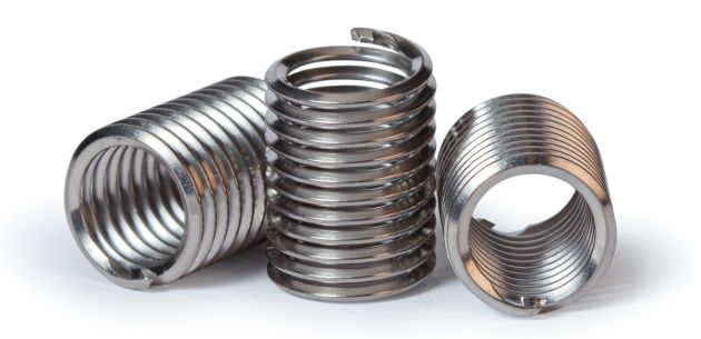
A wire thread insert is a helically coiled fastening device made from high-tensile stainless steel wire (typically Type 304 or 316) with a diamond-shaped cross-section. It is inserted into a pre-tapped hole to create a permanent, wear-resistant internal thread that exceeds the strength of most parent materials. The insert's spring-like design allows it to distribute loads evenly across the entire thread length, transforming shear loading into radial "hoop stress" for superior joint integrity.
Originally developed for aerospace and automotive applications, wire thread inserts serve two primary functions: repairing damaged or stripped threads and reinforcing threads in soft materials such as aluminum, magnesium, and composites. The finished surface (8-16 microinches) is exceptionally smooth, virtually eliminating friction-induced thread erosion and providing corrosion resistance.
Main Types of Wire Thread Inserts
Wire thread inserts are categorized based on their locking mechanism and installation method. The four primary types are:
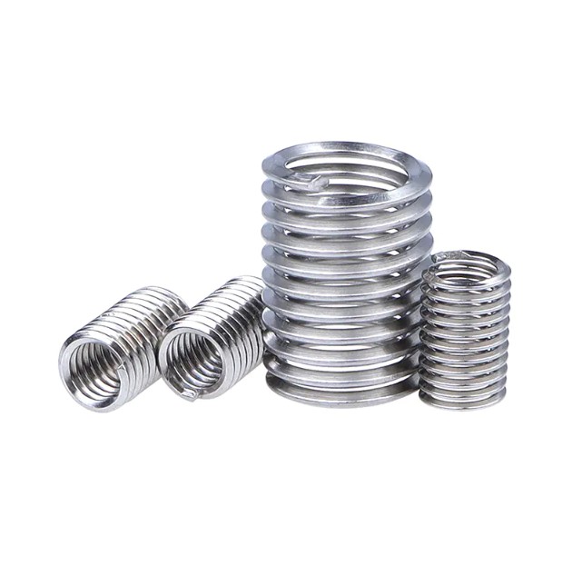
Free-Running (Standard) Inserts
These are the most common type—essentially helically coiled springs that create internal threads matching the bolt size. They provide smooth, free-running threads without any locking feature. Best for: General-purpose applications where frequent assembly/disassembly is required and vibration is minimal.
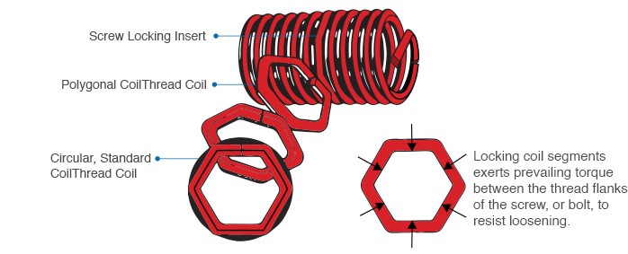
Screw-Locking Inserts
These inserts feature one or more polygonal grip coils that exert radial pressure on the male thread, creating prevailing torque to prevent loosening due to vibration or impact. They eliminate the need for additional locking mechanisms like lock washers or thread-locking compounds. Best for: High-vibration environments such as engines, machinery, and aerospace applications.
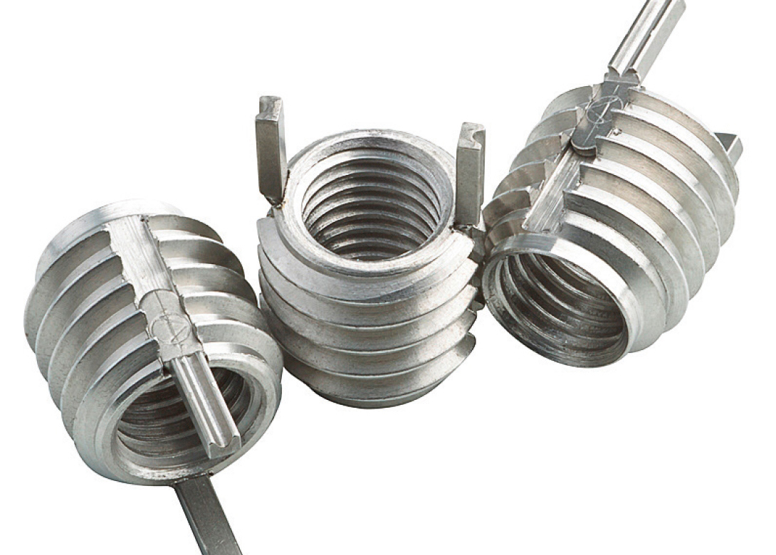
Tanged Inserts
The original design featuring a small tang (installation handle) at one end of the coil. The tang engages with the installation tool and must be broken off after installation. Advantages: Lower cost, established reliability. Disadvantages: Risk of Foreign Object Debris (FOD) from the broken tang, requiring retrieval from blind holes.
Tangless Inserts
A modern innovation featuring drive notches at both ends instead of a tang. These inserts can be installed and removed without breaking off any pieces, completely eliminating FOD risks. Advantages: Reusable, faster installation, no tang retrieval required, ideal for critical aerospace and clean-room applications. Available in: Both free-running and screw-locking configurations.
| Type | Locking Feature | Installation | FOD Risk | Best Application |
|---|---|---|---|---|
| Free-Running | None | Tanged or Tangless | Low-Medium | General assembly |
| Screw-Locking | Radial grip coils | Tanged or Tangless | Low-Medium | High-vibration environments |
| Tanged | Varies | Requires tang break-off | Medium-High | Cost-sensitive applications |
| Tangless | Varies | No break-off required | None | Aerospace, critical systems |
How to Select the Appropriate Model
Selecting the correct wire thread insert requires consideration of four key parameters:
Thread Size and Pitch
Match the insert to your bolt specification (metric: M2–M39; imperial: UNC/UNF #2 through 1/2" and larger). The insert must match both the nominal diameter and thread pitch (coarse or fine) of the fastener.
Insert Length
Insert length is specified as a multiple of the thread diameter (D):
- 1.0D: Minimum engagement, suitable for tight spaces
- 1.5D: Standard length for most applications
- 2.0D–3.0D: Maximum strength for high-load or critical applications
Material Selection
Standard inserts are manufactured from 304 stainless steel (AISI 304, work-hardened to 200,000+ psi tensile strength). For specialized applications:
- 316 stainless steel: Enhanced corrosion resistance for marine/chemical environments
- Inconel X-750: High-temperature applications (up to 550°C/1022°F)
- Phosphor bronze: Applications requiring reduced galling or spark resistance
Surface Treatment
Optional coatings enhance performance in specific conditions:
- Dry Film Lubricant (MolyLube): Reduces friction in high-torque applications, high temperature resistance
- Cadmium or Nickel plating: Superior corrosion resistance, prevents galling during installation
- Silver plating: Extreme temperature applications, reduces thread galling
Required Installation Tools
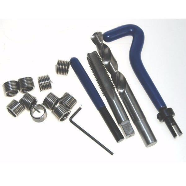
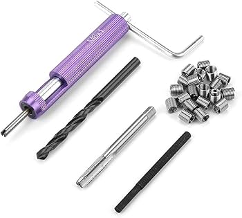
A complete wire thread insert installation requires the following specialized tools:
| Tool | Function | Specification Notes |
|---|---|---|
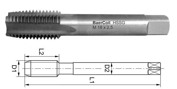
| STI (Screw Thread Insert) Tap | Creates internal threads for insert | Larger pitch diameter than standard tap; must match insert size exactly |
| Core Hole Drill Bit | Drills pilot hole before tapping | Diameter specific to insert size; no tolerances allowed |
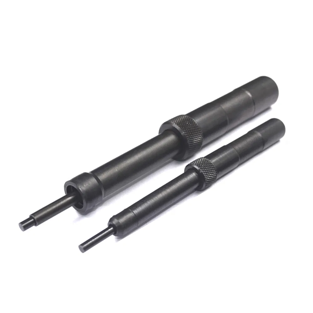
| Insertion Tool (Prewinder) | Winds insert into tapped hole | Manual, electric, or pneumatic; captive or non-captive mandrel types |
| Tang Break Tool | Removes tang after installation | Punch and hammer (200g) for small sizes; specialized break-off tools for larger |
| Countersink | Creates lead-in chamfer | Depth ≤ 0.4 × pitch; prevents insert thread crossing |
| Thread Plug Gauge | Verifies finished thread accuracy | Go/No-Go gauge for quality control |
| Extraction Tool | Removes damaged inserts | Required for repair or replacement scenarios |
Power tool options: For high-volume production, pneumatic or electric installation tools provide consistent installation depth via adjustable depth limits and auto-reverse features.
Correct Installation Procedure
Proper installation follows a precise five-step sequence. Deviations from this procedure are the primary cause of insert failure.
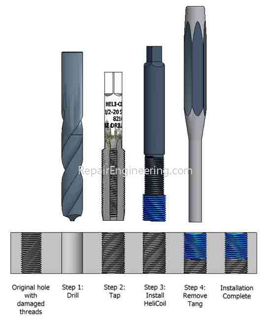
Step 1: Drilling
Using the specified STI drill bit, drill the hole to the correct diameter and depth. Critical requirements: Drilling depth must exceed the insert installation depth by at least 1-2 threads; hole must not be tapered; chips must be completely removed—especially critical for blind holes.
Step 2: Countersinking
Apply a countersink to the hole entrance to prevent thread crossing and provide a lead-in for the insert. Maximum countersink depth: 0.4 × pitch. Excessive countersinking compromises insert retention.
Step 3: Tapping (STI Tap)
Cut threads using the specified STI tap, which creates a larger pitch diameter than standard taps to accommodate the insert's outer diameter. For through holes, tap depth must exceed insert length. For blind holes, use controlled force to prevent tap breakage. Clean threads thoroughly using compressed air (radial nozzles for blind holes) before insert installation.
Step 4: Insert Installation
Mount the insert on the installation tool, engaging the tang (for tanged inserts) or drive notches (for tangless). Rotate the tool to wind the insert into the tapped hole. Stop when the insert is 0.25–0.75 threads below the surface. Avoid applying excessive axial force, which can cause "cross-threading" or insert damage.
Step 5: Tang Removal (Tanged Inserts Only)
For through holes: Position the tang break tool (punch) over the tang and strike the other end of the tool with a 200g hammer to shear off the tang. For blind holes: Use long-nose pliers or extraction tools to retrieve the broken tang. Verify with a thread plug gauge that the finished thread meets specification (typically ISO 2/6H tolerance).
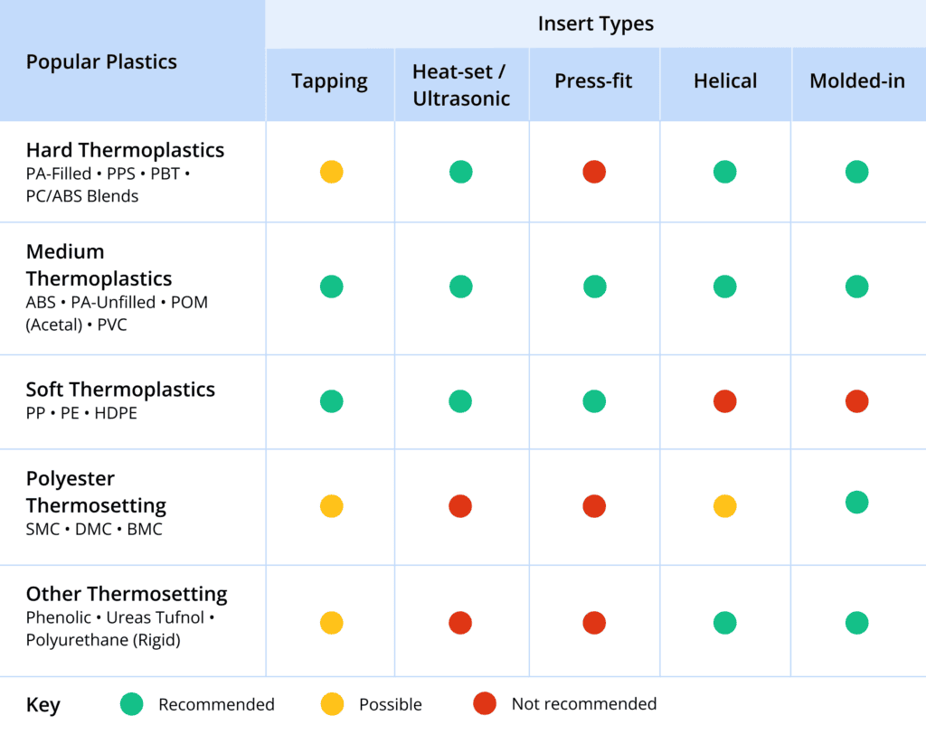
Compatible Materials
Wire thread inserts are compatible with virtually all engineering materials, with particular benefits for softer substrates.
Soft Metals (Primary Applications)
- Aluminum alloys: Most common application; prevents thread stripping in cast and wrought aluminum
- Magnesium alloys: Essential for lightweight aerospace and automotive components
- Copper and bronze: Provides wear resistance in softer non-ferrous metals
- Titanium: Compatible but often used for thread repair rather than primary reinforcement
Ferrous Metals
While less commonly needed in steel (which has adequate thread strength), inserts are used in cast iron and ductile iron for wear resistance and in steel applications requiring frequent assembly/disassembly to prevent thread wear.
Non-Metallic Materials
Effective in thermoplastics, thermosets, and composites (carbon fiber, fiberglass) where direct threads would strip easily. The insert's radial pressure creates mechanical locking without stress concentrations that cause cracking in brittle materials.
Material hardness guideline: Inserts are most beneficial when parent material hardness is below 30 HRC (Rockwell C). In harder materials, inserts provide corrosion resistance and thread life extension rather than strength enhancement.
Handling Overtightening and Breakage
Installation failures require systematic remediation to restore thread integrity.
Overtightened Insert Removal
When an insert is overtightened or improperly seated, use a specialized extraction tool. Insert the tool tip into the insert coil, press firmly, and rotate counterclockwise to back out the insert. For stubborn cases, apply penetrating oil and allow it to soak before extraction attempts.
Broken Insert Removal
If the insert breaks during installation:
- Drill out the broken insert using a drill bit slightly smaller than the STI tap drill size to avoid damaging the parent threads
- Use a tap extractor or easy-out tool to remove remaining coil fragments
- Inspect the tapped hole for damage; if threads are compromised, drill out to the next larger insert size or use a solid bushing insert (Keensert) for repair

Prevention Measures
To prevent overtightening:
- Use torque-limiting installation tools or preset torque wrenches
- Stop installation when the insert is 0.25–0.75 threads below the surface—never flush or protruding
- Verify tap depth is sufficient before installation; insufficient depth causes "bottoming out" and coil distortion
- Use proper lubrication during tapping to prevent galling that can cause insert binding
Frequently Asked Questions
Can wire thread inserts be reused?
Tangless inserts can be removed and reused multiple times without damage. Tanged inserts can technically be removed but the tang break-off makes reuse impractical. For applications requiring frequent maintenance, specify tangless inserts from the outset.
How much stronger is a threaded hole with an insert?
A properly installed wire thread insert provides a thread that is 20% stronger than the original parent material thread in tension and significantly superior in shear. The load distribution across the full insert length versus concentration on the first 2-3 threads of a standard tapped hole provides the primary strength advantage.
Do inserts affect bolt torque specifications?
Screw-locking inserts require higher installation torque (typically 1.5–2× standard) due to the prevailing torque from the grip coils. Free-running inserts use standard torque values. Always verify with the insert manufacturer's specifications, as under-torquing can cause loosening while over-torquing risks bolt failure.
Are wire thread inserts standardized?
Yes, most inserts conform to DIN 8140 (European), NASM 21209 (Aerospace), or MS21209 (Military Standard). This standardization ensures compatibility between manufacturers for inserts, taps, and installation tools, though verification is recommended for critical applications.
Can inserts be installed in blind holes?
Yes, both tanged and tangless inserts work in blind holes. For tanged inserts in blind holes, ensure the hole depth accommodates the full insert length plus tang break-off clearance. Tangless inserts are particularly advantageous for blind holes as they eliminate the risk of loose tangs remaining in the cavity.
What causes insert "spinning" or pull-out?
Insert rotation in the parent hole indicates insufficient radial pressure, usually caused by: (1) incorrect STI tap size resulting in oversized threads, (2) installation in material below minimum hardness/shear strength, or (3) using too short an insert length for the load. Remediation requires drilling out and installing a larger insert or switching to a key-locking solid insert.