

 Français
 Español
 Deutsch


Content
- 1 Brass Threaded Inserts for Plastic: What They Are and Where They Fit
- 2 The Five Anchor Styles You Will Meet in Thermoplastic Assemblies
- 3 Heat-Set, Ultrasonic or Moulded-In: Picking the Setting Method
- 4 Boss and Hole Geometry: The Numbers That Decide Pull-Out
- 5 Relative Performance by Insert Style: What the Bars Show
- 6 When Brass Is Not Enough: Steel Inserts in the Same Boss
- 7 Installation Sequence and the Failures That Follow
- 8 Specifying Brass Threaded Inserts for Plastic on an RFQ
- 9 Repair, Reuse and Service Checks
- 10 Where to Go Next on This Site
- 11 Frequently Asked Questions
- 11.1 Are brass threaded inserts for plastic strong enough for structural joints?
- 11.2 What hole size do I need for an M4 brass heat-set insert?
- 11.3 Can brass inserts be installed without heat?
- 11.4 Do brass inserts work in glass-filled nylon?
- 11.5 Are brass inserts suitable for 3D printed parts?
- 11.6 What torque can a brass insert take?
- 11.7 How do I choose between a brass insert supplier and a steel insert manufacturer?
An M4 brass insert pulling out of a glass-filled nylon boss at 600 N, when the drawing asks for 900 N, is rarely a brass problem. In most of the failure reports that cross a factory desk, the insert was within tolerance; the boss was 1.5 mm too small, the hole was drilled 0.15 mm oversize, and the setting iron was running 30 °C too hot. Brass threaded inserts for plastic only behave the way the drawing promises when the insert profile, boss wall, hole tolerance, setting method and driving torque are treated as one system.
This guide works through that system: what brass inserts actually do in thermoplastics, how the five common anchor styles behave, which geometry numbers control pull-out and torque, how heat-set and ultrasonic setting compare in production, and what belongs on a purchase order when you buy inserts by the hundred thousand. It is written for design engineers, process engineers and buyers who need a part that survives the assembly line and a dozen service cycles.
Conclusion first: brass is the default insert material for heat-set and moulded-in threads in plastic because it machines cleanly and conducts heat evenly, but boss and hole geometry decide the result far more than the alloy does.
Brass Threaded Inserts for Plastic: What They Are and Where They Fit
A brass threaded insert is a machined or cold-formed bush with an internal metal thread and a profiled outside surface, knurled, grooved, flanged or plain, that is anchored into a thermoplastic boss. Its purpose is narrow and valuable: it gives a moulded part a reusable thread that can be assembled, disassembled and re-torqued without the polymer creeping, cold-flowing or stripping out.
Brass earns that role for four practical reasons. It machines to tight tolerances without burrs, so hole and thread dimensions stay consistent from lot to lot. Its thermal conductivity, roughly 120 W/m·K for common free-cutting grades, spreads heat quickly during thermal or ultrasonic setting, which means the polymer melts around the knurl instead of scorching at the surface. Free-cutting brass offers tensile strength in the region of 350-450 MPa, comfortably above what most unreinforced thermoplastic joints can mobilise. And it does not gall against steel screws the way stainless-on-stainless assemblies can.
The limits matter just as much. Brass softens noticeably above about 200 °C, dezincifies in some aggressive chemical and marine environments, and adds weight. When a joint needs more than the polymer or the brass can deliver, the answer is usually a steel insert rather than a bigger brass one.
| Insert material | Typical styles | Relative joint strength | Best used when | Watch-outs |
|---|---|---|---|---|
| Free-cutting brass (lead-free grades available) | Heat-set, ultrasonic, moulded-in, press-in | Moderate | General assembly, repeated disassembly, 3D printed parts, appliance and electronics housings | Softens if setting temperature runs high; not for continuous service above roughly 200 °C |
| Stainless steel A2 / A4 | Self-tapping, key-locking, moulded-in | High | Corrosive atmospheres, high torque, elevated temperature, safety-related joints | Higher driving torque, thread galling risk, heat setting is impractical |
| Carbon steel, zinc plated | Self-tapping, three-hole | High | Cost-driven volume programmes in dry indoor conditions | Coating can be damaged in cutting slots; corrosion if condensation is present |
| Aluminium | Press-in, moulded-in | Low to moderate | Weight-critical housings | Lower wear resistance, higher galling risk on repeated assembly |
Brass is the right starting point for heat-set and moulded-in threads, but it is a joint material, not a structural one; the polymer boss carries the load and brass simply distributes it.
The Five Anchor Styles You Will Meet in Thermoplastic Assemblies
Heat-set and ultrasonic brass inserts
A brass bush with a knurled or grooved outside diameter is pressed into a moulded hole while the surrounding polymer is softened by a heated tip or ultrasonic horn. Once the polymer re-freezes around the knurl, the insert is mechanically locked. This is the most common route for brass threaded inserts for plastic because it can be added after moulding, needs no mould modification, and tolerates design changes late in a programme.
Moulded-in inserts
The insert is placed on a mould core and encapsulated during injection. The result is the strongest and most consistent brass joint available, with no secondary operation and no risk of operator error at the setting station. The trade-offs are tooling complexity, longer cycle time, and the fact that a misplaced insert scraps the whole moulding.
Self-tapping (thread-forming) steel inserts
These are driven into a plain moulded or drilled hole with a setting tool; cutting slots or a thread-forming profile engage the polymer directly. They suit higher torque and higher temperature than brass, and they are widely used in automotive and appliance assemblies where a steel screw will be driven repeatedly. Installation is fast, but hole diameter has to be held tightly because the insert forms its own thread rather than melting into place.
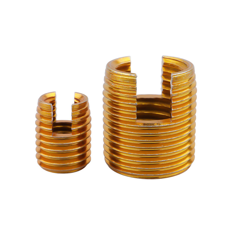 Carbon Steel Self-Tapping Thread InsertA carbon steel self-tapping insert that cuts threads in plastics and soft metals, suited to repeated screw use and fast installation.View Product →
Press-in inserts
A knurled or flanged bush is pushed into a moulded hole, usually with a simple press. Tooling cost is low and cycle time is short, but retention depends almost entirely on interference fit, so press-in inserts are best for lightly loaded threads and brittle or highly filled resins where heat setting would crack the boss.
Expansion inserts
A slotted sleeve expands as the screw is driven, gripping the hole wall from inside. They are convenient for repair and for thin panels, but they concentrate stress at the slot ends and offer the least resistance to repeated torque. Treat them as a service solution rather than a first-choice production design.
Choose the anchor style before choosing the material: heat-set brass wins on flexibility, moulded-in brass wins on consistency, and self-tapping steel wins when torque and temperature exceed what brass can hold.
Heat-Set, Ultrasonic or Moulded-In: Picking the Setting Method
Once a brass insert has been selected, the setting method decides cycle time, equipment cost and the size of the quality problem you inherit. Thermal setting with a heated tip is the cheapest entry point; ultrasonic setting is faster and more repeatable at volume; moulding-in removes the setting station entirely but moves the risk into the tool.
| Method | Typical cycle | Tooling investment | Repeatability | Suits |
|---|---|---|---|---|
| Thermal / heat-set | 3-8 seconds per insert | Low | Operator dependent | Low to medium volume, large inserts, prototypes |
| Ultrasonic | 1-3 seconds per insert | Medium to high | High, once parameters are locked | High volume, small to medium inserts, multi-insert parts |
| Moulded-in | Adds 5-20 seconds to the mould cycle | High, tool modification | Very high | Safety-critical parts, very high volume, tamper-proof assemblies |
| Press-in | 1-2 seconds per insert | Low | Medium, fit dependent | Light loads, brittle resins, thin bosses |
Two process details separate a stable line from a line that reworks. First, the insert should be at or slightly below ambient temperature when it enters the boss; a brass insert that has been sitting in a hot bin expands and shaves polymer instead of melting into it. Second, hold time matters more than peak temperature. Pulling the setting tip away early leaves the polymer elastic rather than molten, and the insert backs out a few tenths of a millimetre overnight.
Ultrasonic setting pays for itself above roughly 300,000 inserts a year; below that, heat setting with a controlled tip and a documented hold time is usually the better commercial decision.
Boss and Hole Geometry: The Numbers That Decide Pull-Out
Most insert failures are geometry failures. The three dimensions that matter are hole diameter, boss outside diameter and boss depth, and all three should be treated as toleranced features rather than nominal values on a sketch.
Hole diameter is the tightest of the three. For a brass heat-set insert, the moulded hole is normally the insert's minor diameter plus 0.05 to 0.15 mm, held to plus or minus 0.05 mm. Too small and the polymer has nowhere to go, so the boss splits; too large and there is not enough melt to fill the knurl, and the insert pulls out cleanly with polymer dust in the knurl.
Boss outside diameter should usually be at least twice the insert outside diameter, which puts a minimum wall of about half the insert diameter around the thread. Boss depth should exceed insert length by 0.5 to 1.0 mm so displaced melt has somewhere to flow instead of pushing the insert back out. A 0.5 mm radius at the boss root removes the stress concentration that turns a marginal pull-out result into a crack.
| Thread | Insert OD (mm) | Moulded hole (mm) | Boss OD (mm) | Minimum wall (mm) | Boss depth (mm) |
|---|---|---|---|---|---|
| M2 | 3.6 | 3.5 | 6.0 | 1.2 | Insert length + 0.5 |
| M2.5 | 4.2 | 4.1 | 7.0 | 1.4 | Insert length + 0.5 |
| M3 | 4.9 | 4.8 | 8.0 | 1.5 | Insert length + 0.5 |
| M4 | 6.3 | 6.2 | 10.0 | 1.8 | Insert length + 1.0 |
| M5 | 7.9 | 7.8 | 12.0 | 2.0 | Insert length + 1.0 |
| M6 | 9.5 | 9.4 | 14.5 | 2.5 | Insert length + 1.0 |
| M8 | 12.0 | 11.9 | 18.0 | 3.0 | Insert length + 1.5 |
Reinforced resins change the calculation. Glass fibres reduce the melt's ability to flow around a knurl, raise the modulus, and make the boss far more sensitive to hoop stress, so a 30 percent glass-filled polyamide typically needs a 15 percent larger boss and slower setting. Crystalline resins such as POM and PBT shrink more than amorphous ones, which means hole diameter measured cold may sit 0.05 mm off once the part has stabilised.
Hold hole diameter to plus or minus 0.05 mm and keep the boss wall at half the insert diameter; these two decisions remove the majority of pull-out and cracking complaints before the tool is even cut.
Relative Performance by Insert Style: What the Bars Show
Insert performance is usually discussed as a single number, which hides the trade-offs that matter on a real line. The chart below separates the styles by a composite retention index that combines first-pull-out load with the ability to survive repeated assembly cycles. Values are indexed so that a fully encapsulated moulded-in brass insert equals 100. The comparison assumes an unfilled polyamide 66 boss designed to the geometry guidance above. It is a planning tool for early design decisions, not a substitute for a pull-out test on your own moulding. Real numbers will move with wall thickness, melt temperature, insert knurl geometry and screw torque. The ranking, however, is stable across most commodity thermoplastics.
Composite retention index by insert style (moulded-in brass = 100)
Illustrative ranking for unfilled PA66 bosses; compare relative position, not absolute values
Moulded-in brass 100
Heat-set brass 92
Self-tapping steel 85
Press-in brass 72
Expansion insert 64
The gap between moulded-in and heat-set brass is small, roughly eight index points, and that is the most useful message in the chart. A heat-set insert with a properly sized boss recovers almost all of the performance of the more expensive moulded-in route, because the limiting factor is the polymer volume around the knurl rather than the encapsulation itself. Buyers who insist on moulded-in geometry for every part are often paying tooling money for strength the assembly does not need.
The self-tapping steel bar sits slightly below heat-set brass on composite retention, but that single figure hides an important split. Steel self-tapping inserts usually beat brass on peak torque and on temperature resistance, and they lose on reusability, because each removal cycle enlarges the formed thread in the polymer. If a joint will be opened three times in service, brass is the safer default; if it will be driven once to a high torque and never touched, steel is the better engineering choice.
The press-in and expansion bars fall away steeply, and the reasons are mechanical rather than metallurgical. Neither style creates a melt bond, so retention depends on interference and friction alone, both of which relax as the polymer creeps under sustained load. That relaxation is accelerated by temperature: a press-in insert that holds 400 N at 23 °C may hold noticeably less after a week at 60 °C.
What the chart cannot show is scatter. Heat-set results spread far more widely than moulded-in results, because setting is a manual or semi-manual process with dozens of small variables. A well-run line can push heat-set inserts close to the moulded-in figure; a line with a worn tip and no hold-time control can drop below the press-in bar. Process discipline, in other words, is worth more than a material upgrade at this level of performance.
Heat-set brass recovers most of the performance of moulded-in brass at a fraction of the tooling cost, so reserve moulded-in geometry for safety-critical or extremely high-volume assemblies.
When Brass Is Not Enough: Steel Inserts in the Same Boss
Brass covers the majority of thermoplastic thread requirements, but three conditions push a design toward steel: service temperature above roughly 200 °C, torque requirements that strip a brass thread, and load paths where the joint is classified as safety-related. In those cases the boss geometry stays similar and the insert family changes.
Brass wins when
|
Steel wins when
|
Our own production is concentrated on steel-based thread inserts, including self-tapping, wire thread, key-locking and three-hole designs, together with the installation and extraction tooling that goes with them. That focus is deliberate: it sits where automotive, aerospace and rail programmes need documented strength and repeatable pull-out. Brass heat-set inserts remain the right answer for a large share of plastic housings, and buyers often source both families from the same supplier so that torque specs, plating and inspection standards stay aligned.
For very high load cases, a key-locking insert carries the load through keys driven into the surrounding material rather than through friction alone. In a plastic boss this is over-engineering for most applications, but in a metal housing with a damaged thread it is often the only repair that restores full-rated torque.
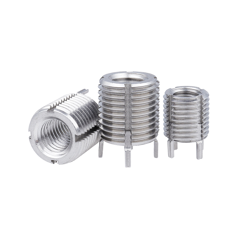 Key-Locking Thread Insert for High-Load ApplicationsA key-locking insert in steel or stainless steel for high-load, high-vibration bosses where frequent disassembly or damaged metal threads need repair.View Product →
Specify brass for reusability and steel for load: the two families solve different problems in the same boss, and mixing them within one assembly is normal practice.
Installation Sequence and the Failures That Follow
A repeatable installation process is short enough to write on one page, and skipping any step shows up as a specific defect within a few hundred parts.
- Verify hole diameter with a plug gauge, not with a caliper on a moulded part.
- Clear the hole of flash and mould release residue; a contaminated hole creates a weak melt bond.
- Set the tip or horn temperature and confirm it with a contact thermometer at the start of each shift.
- Insert vertically, with the insert axis within 1 degree of the boss axis.
- Apply heat and pressure until the insert shoulder meets the boss face, then hold without pressure.
- Allow the assembly to cool before handling; moving a warm insert shears the melt bond.
- Record pull-out and torque results per lot, not per year.
| Symptom | Likely cause | First corrective action |
|---|---|---|
| Insert backs out after cooling | Hole oversize or hold time too short | Reduce hole diameter by 0.05 mm, extend hold time |
| Radial crack in the boss | Wall too thin, sharp root, excessive interference | Increase boss OD, add 0.5 mm root radius, cool the insert before setting |
| Insert spins under torque | Knurl filled with flash, hole too deep | Check hole depth and insert length, consider a flanged variant |
| Thread stripped at assembly | Over-torque or engagement below one diameter | Publish a torque spec, increase engagement, review insert material |
| Boss fails at a weld line | Gate positioned opposite the boss | Relocate the gate or raise melt temperature |
Setting tools deserve the same attention as the insert. A worn tip loses contact area, which forces the operator to push harder and longer, and that combination is exactly what cracks bosses. Keep a spare tip on the line and replace it on a defined cycle count rather than when someone notices a problem.
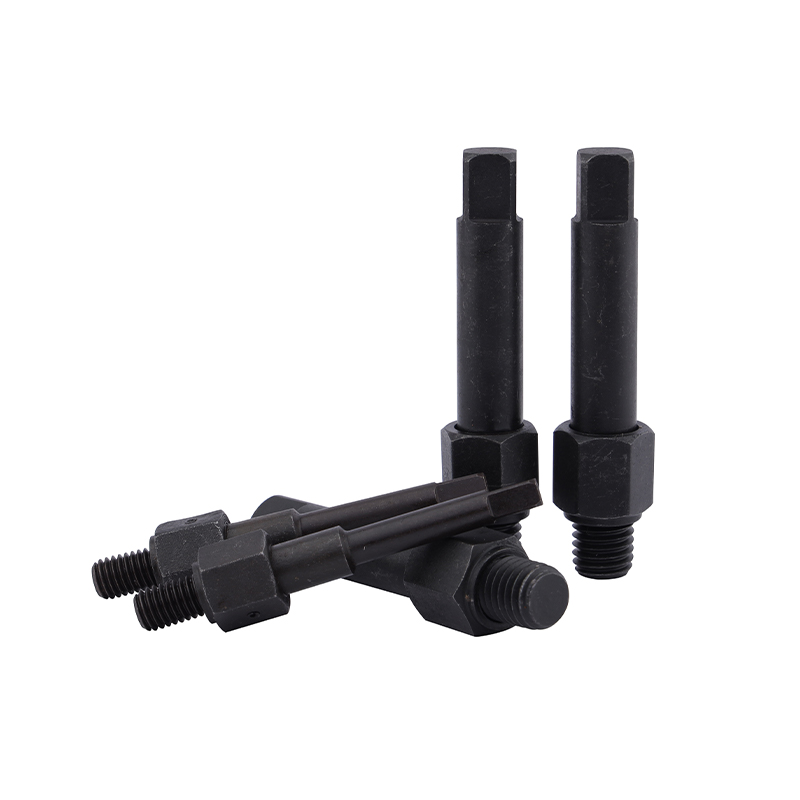 Self-Tapping Insert Installation Tool for Plastics and Light AlloysA guided installation tool for self-tapping inserts, with adjustable torque and wear-resistant alloy steel construction for stable setting in plastics and light alloys.View Product →
Control the hole, the hold time and the tool tip, and the defect list above shrinks to almost nothing; change the insert supplier and none of those three improve.
Specifying Brass Threaded Inserts for Plastic on an RFQ
An insert is a low-cost part with a high cost of failure, so the purchasing document should read like an engineering document. The following points are the ones that most often cause a lot to be rejected on arrival, or worse, to pass incoming inspection and fail at the customer.
- Alloy designation and temper, plus a lead-free requirement if the application is regulated.
- Thread class and gauge type, for example 6H with a go/no-go check on every lot.
- Outside diameter, knurl geometry and shoulder height with explicit tolerances.
- Plating or passivation specification and a minimum coating thickness where relevant.
- Insert length tolerance and squareness of the shoulder to the axis.
- Lot traceability from raw material heat number to shipping carton.
- First article inspection report and a dimensional layout on the first production lot.
- Packaging that prevents knurl-to-knurl contact damage in transit.
- Agreed sampling plan and the measurement method for each critical dimension.
- Stated MOQ, replenishment lead time and change-notification procedure.
On the commercial side, the questions worth asking a manufacturer are less about price per thousand and more about stability. Can they hold the same knurl geometry across a five-year programme? Do they inspect the minor diameter or only the thread? Will they quote the installation tooling with the insert so the process is validated as a package? A wholesaler or distributor can be a perfectly good partner for standard sizes, but for anything with a drawing revision, a direct manufacturer relationship usually shortens the problem-solving loop.
Finally, ask for the certificate package before the first shipment rather than after. A quality management system certificate, a material certificate and a plating certificate together take minutes to send and save weeks of argument if a customer audit arrives unexpectedly.
The cheapest insert is the one that never generates a containment report; specify tolerances, traceability and tooling together, and treat supplier stability as part of the price.
Repair, Reuse and Service Checks
Sooner or later an insert strips. The repair route depends on how much material surrounds the boss and how much load the joint still has to carry.
- If the thread is damaged but the insert is sound, chase the thread with a tap of the correct class before considering replacement.
- If the insert spins, remove it with an extraction tool, clean the hole and install an oversize insert of the same family.
- If the boss is cracked, the repair is a mechanical one: a larger boss sleeve, a key-locking insert, or a redesigned joint.
- If the failure repeats at the same station, stop repairing and investigate the torque driver calibration.
Reuse limits are worth writing into the maintenance procedure. A brass thread in plastic typically tolerates dozens of assembly cycles at moderate torque, but the polymer around it creeps a little on every cycle. A joint that held 5 N·m when new may only hold 3.5 N·m after twenty cycles, and the drop is invisible until a leak or a rattle appears.
Repair is a symptom management tool; if the same insert fails twice on the same line, the driver torque or the hole diameter is the real defect.
Where to Go Next on This Site
Two pages cover most of what a buyer or design engineer needs after reading this guide.
| Purpose | What you will find |
|---|---|
| Product range overview | Self-tapping, wire thread, key-locking and three-hole inserts, internal-external thread conversion nuts, oil plugs, taps and installation tooling, organised by structure, material and coating. |
| Contact the factory | Send a drawing, a resin grade and a torque target, and the engineering team can propose an insert family, a boss geometry check and a sample plan. |
Bring the resin grade and the torque target to the conversation; an insert recommendation without those two inputs is only a guess.
Frequently Asked Questions
Are brass threaded inserts for plastic strong enough for structural joints?Usually not on their own. A brass insert in a correctly sized boss can carry several hundred newtons of pull-out and a few newton metres of torque, which covers housings, brackets and enclosures. Structural joints that see continuous load, vibration or safety requirements normally move to a steel insert with a larger boss, or to a metal-to-metal fastening entirely. |
What hole size do I need for an M4 brass heat-set insert?For an insert with a 6.3 mm outside diameter, the moulded hole is typically 6.2 mm, held to plus or minus 0.05 mm. Glass-filled resins often need the tight end of that band. Always confirm against the insert drawing, because knurl depth and shoulder design shift the correct value by a few hundredths of a millimetre. |
Can brass inserts be installed without heat?Yes, through press-in or self-tapping styles, but a heat-set insert forced into a cold hole will shear polymer and sit loose. If you have no heat-setting equipment, choose a press-in or thread-forming insert designed for cold installation rather than adapting a heat-set part. |
Do brass inserts work in glass-filled nylon?They do, with adjustments. Glass fibre reduces melt flow around the knurl and raises the risk of boss cracking, so the boss should be roughly 15 percent larger, setting temperature slightly higher and hold time longer than for unfilled resin. Pre-heating the part or using ultrasonic setting improves consistency. |
Are brass inserts suitable for 3D printed parts?They are the standard solution for printed prototypes and small production runs. Printed walls are usually weaker and less uniform than moulded ones, so the boss should be printed solid, with at least three perimeters around the hole, and the hole diameter reduced slightly to compensate for print tolerance. Heat setting with a controlled tip works well on PLA, PETG and ABS. |
What torque can a brass insert take?It depends on thread size, engagement length and resin, but the practical limit is usually set by the polymer rather than the brass. A safe starting point is the torque that produces roughly 60 percent of the joint's measured strip torque, verified by test on the actual moulding rather than by calculation alone. |
How do I choose between a brass insert supplier and a steel insert manufacturer?Start from the joint requirement, not the material. If the part needs repeated assembly and moderate load, a brass insert supplier is the right conversation. If the joint needs maximum pull-out, high torque or elevated temperature, speak to a manufacturer that produces steel inserts and matching installation tooling, so the process and the part are validated together. |
Every question above resolves to the same two inputs: the resin grade and the boss geometry; get those right and the insert choice becomes straightforward.


